


Here we give a brief overview of the Design and simulation results of the Maximum Peak Detection and Auto-Tuning Control Circuit for MCR-WPT Coils.
Below is a list of all the topics we cover in this page. Go ahead and click on any of these links, and you’ll be taken to that specific section.
MCR-WPT Coils suffer from reduced efficiency when their separation distance is less than the optimal distance for peak transfer efficiency, due to a phenomenon known as frequency splitting. For more information about this efficiency problem that the Maximum Peak Detection and Auto-Tuning Control Circuit is designed to overcome, click on button on the right to find out more.
Our Maximum Peak Detection system is comprised of 3 main circuit blocks, namely:
There are a few key factors that needed to be considered when designing each circuit block of the Maximum Peak Detection system.
For a brief overview of these key design factors for each circuit block, click on the respective button to find out more.
When we combine these circuit block together, we are able to detect the maximum tuning peak output voltage of the MCR-WPT Coils, and thereby improve power transmission efficiency. A description of its operation and tuning range can be retrieved by clicking on the button below.
The Auto-Tuning system is comprised of 3 main circuit blocks, namely:
There are a some key factors that need to be considered when designing each circuit block of the Maximum Peak Detection system.
For a brief overview of these key design factors for each circuit block, click on the respective button to find out more.
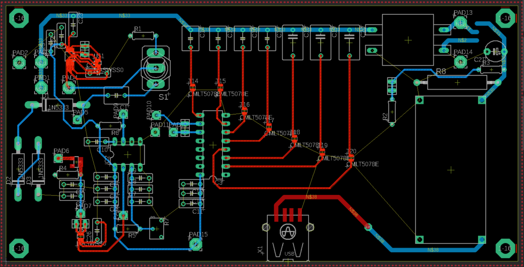
For an overview of the devices used in the simulation design, some simulation results, and to view a preliminary prototype layout, click on the respective button to find out more.
Tuning time, tuning capacitance and bridge rectifier output power at different distances before tuning and at maximum efficiency.
| MCR-WPT Coil Design | Separation Distance | Output Power Before Tuning | Peak Output Power | Tuning Capacitance | Output Power Increase | Tuning time |
|---|---|---|---|---|---|---|
|
5in x 2.5in |
0.5In |
1.388W |
4.725W |
3100pF |
240% |
1.033ms |
|
1.0In |
5.38W |
8.002W |
1200pF |
49% |
0.295ms |